Installation Instructions of MSCJ for ACSR Conductor

Compression Splice for ACSS and ACSS/TW Conductors
Installation Instructions
Mark the conductor a distance of ½ the length of the aluminum sleeve 
Prior to making connection, the outer strands of the conductor should be cleaned with a wire brush or abrasive cloth
Remark each conductor half the length of the aluminum sleeve, if the mark was removed during wire brushing prior to any strand cutting, tape the end of each conductor to help maintain the round contour
Slide the aluminum sleeve over one conductor until sufficient working length   protrudes from end 
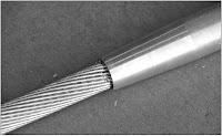
Cut back aluminum strands of both conductors ½ the length of the steel sleeve plus 1 ½ inch (38 1 mm) Do not nick the steel strands File any burrs, if present 

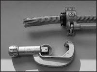
Use of a cable trimming tool is recommended
Insert ends of steel core into steel sleeve making sure the ends butt solidly against   center stop 
Using the proper SH die set, compress steel sleeve full length making initial  compression over center of sleeve 
Overlap  each successive compression by at least ¼ inch (6.4 mm) Complete die closure is required on all compressions
  
Slide the aluminum sleeve over the installed steel sleeve, centering between the two marks that were made in Step 3 


Inject AFCHT filler compound into filler hole until compound emerges from both ends of aluminum sleeve

Insert and drive filler plug (cavity up) into hole and peen edge of hole over top surface of plug  Leaving the filler plug in the small plastic bag makes it easier to insert when working with gloves 


Using the proper AH die set, make the initial compression at the “start” mark on one side of center

 The second compression should be made at the other “start” mark on opposite side of center  Continue  making  compressions  to the  end,  overlapping each by at least ¼ inch (6 4 mm)
 Complete die closure is required for each compression Note:  A light oil coating on the die grooves and aluminum sleeve is recommended
Compressed portion of splice sleeve should   have a smooth uniform appearance if die flash is present, remove with a file or emery cloth Remove any excess filler compound which may have been forced out the ends of the splice 


Installation Instructions Dead End for ACSR Conductor

Standard Compression Dead End for ACSR and ACSS Conductor
Installation Instructions
CAUTION: ACSR Dead Ends Cannot Be Used on ACSS HT Conductor

Mark the conductor a distance of 3/4 the length of the aluminum body
Prior to making connection, the outer strands of the conductor must be cleaned with a wire brush or abrasive cloth Prior to any strand cutting, tape the end of the conductor to help maintain the round contour.

Slide the aluminum dead end body over conductor until sufficient working length protrudes from tongue end.

Cut back aluminum strands equal to the depth of the steel forging barrel plus 1 inch (254 mm)Do not nick the steel strands File burrs, if present.


Use of a cable trimming tool is recommended 


Use of a cable trimming tool is recommended

Insert steel core into steel barrel to full length of bore 

Using the proper SH die set, compress steel barrel full length making initial compression adjacent to rib closest to barrel Overlap each successive compression by at least ¼ inch (64 mm) Complete die closure is required on all compression. 

Slide the aluminum body over the steel forging until the tongue end butts solidly against felt washer and shoulder of steel eye Align eye with tongue to desired orientation for attachment to insulator string 


Inject filler compound into filler hole until compound emerges at felt washer and t Insert and drive filler plug (cavity up) 


Into hole and peen edge of hole over top surface of plug 


Leaving the filler plug in the small plastic bag makes it easier to insert when working with gloves
Using the proper AH die set, make the initial compression on the aluminum body beginning at the “start” mark nearest the tongue  Overlap each successive compression by at least ¼ inch (6 4 mm)  Press only to the “stop” mark  Complete die closure is required for each compression 
Note: A light oil coating on the die grooves and aluminum sleeve is recommended
To press the dead end body over the conductor, use the same die used in step 11  Begin compressing at the “start” mark about centrally located  Overlap each successive compression by at least ¼ inch (6.4mm)  Press to the end of the body, including the tapered portion  Complete die closure is required on each compression 


During this compression sequence, the plastic bag in which the dead end assembly was received can be used as a medium between the aluminum body and dies (instead of oil as mentioned in step 11)


Compressed portion of dead end body should have a smooth uniform appearance if die flash is present, remove with a file or emery cloth Remove any excess filler compound  which may have been forced out the end of the dead end body  

Dead End Clamp for ACSR Conductors


Sl No
ACSR Code Name
DIA
A
ALUMINUM SLEEVE
STEEL SLEEVE
No of Bolts
ØD1
ØD2
X
Y
ØD3
ØD4
X
Y
1
RACCOON
12.27
394
15.3
24.0
23.4
20.2
05.00
12.2
11.7
10.1
2
2
DOG
14.15
394
16.7
30.0
29.4
25.0
05.00
12.2
11.7
10.1
2
3
LEOPARD
15.84
394
18.3
30.0
29.4
25.0
05.60
12.2
11.7
10.1
2
4
COYOTE
15.86
394
18.3
30.0
29.4
25.0
06.00
12.2
11.7
10.1
2
5
TIGER
16.52
457
18.6
33.0
35.6
28.0
07.30
15.2
14.7
12.7
2
6
WOLF
18.13
419
20.6
33.0
32.6
28.0
08.00
15.2
14.7
12.7
2
7
ORIOLE
18.82
419
21.8
33.0
32.6
28.0
08.40
18.0
17.4
15.1
2
8
LYNX
19.53
457
21.8
38.0
37.0
32.0
08.70
18.0
17.4
15.1
2
9
LARK
20.47
457
23.0
38.0
37.0
32.0
09.10
18.0
17.4
15.1
2
10
PANTHER
21.00
457
23.0
38.0
37.0
32.0
09.40
18.0
17.4
15.1
2
11
LINE
22.26
457
24.6
38.0
37.0
32.0
10.50
19.2
18.5
16.1
2
12
BEAR
23.45
508
25.0
43.0
41.0
36.0
10.30
19.2
18.5
16.1
2
13
GROSBEAK
25.16
457
27.0
43.0
41.0
36.0
09.80
19.2
18.5
16.1
2
14
TEAL
25.24
600
27.5
43.0
41.0
36.0
11.20
19.2
18.5
16.1
2
15
GOAT
25.97
508
29.0
43.0
41.0
36.0
11.50
19.2
18.5
16.1
3
16
ANTELOPE
26.73
508
29.0
43.0
41.0
36.0
09.30
18.0
17.4
15.1
3
17
KUNDAH
26.80
508
29.0
43.0
41.0
36.0
06.20
12.2
11.7
10.1
3
18
SHEEP
27.93
559
30.0
48.0
46.0
40.0
12.30
24.0
23.4
20.2
3
19
DRAKE
28.14
559
31.0
48.0
46.0
40.0
10.70
19.2
18.5
16.1
2
20
ZEBRA
28.62
559
31.0
48.0
46.0
40.0
09.95
19.2
18.5
16.0
3
21
DEER
29.89
597
33.0
54.0
53.0
46.0
13.10
24.0
23.4
20.2
4
22
CAMEL
30.15
559
32.0
48.0
46.0
40.0
10.50
21.0
20.2
17.5
3
23
ELK
31.50
597
34.0
54.0
53.0
46.0
14.00
24.0
23.4
20.2
4
24
MORKULLA
31.68
597
34.0
54.0
53.0
46.0
07.50
15.2
14.7
12.7
4
25
MOOSE
31.77
597
34.0
54.0
53.0
46.0
11.10
21.0
20.2
17.5
4
26
BERSIMIS
35.05
635
37.4
58.4
57.4
49.7
08.10
20.7
20.2
17.5
4

NOTE: - The compression Type Dead End Clamps and Jumpers are manufactured form extruded Aluminum / Aluminum Alloy Tube and flat Bars. The steel sleeves are made of forged steel duly hot dip galvanized.
The dimensions of Aluminum Dead End & Steel Dead Ended on the dimension, electrical & mechanical properties of conductors. These clamps have conductivity equal to that of the conductor and develop slip strength upto 95% of the conductor.