Introduction
Transpositions, or the re-positioning of
phases on power lines, has been done since the 1920s. Transpositions for telephone
circuits have been utilized since the early 1900s. The majority of the power
line transpositions were installed prior to the 1980s. There can be several
reasons for installing transpositions which must be thoroughly evaluated in the
engineering phase. Transpositions are installed when the transmission lines are
initially constructed – it is a rare case when transpositions are added after a
line is in service. The reasons for installing transpositions are theoretical
in nature and can be difficult for students to understand. The objective of
this paper is to simplify explanations regarding what transpositions are, why
they are installed, and where they are installed.
Definition
A transposition is a physical rotation of
the conductors that results in each conductor or phase being moved to occupy
the next physical position in a regular sequence. After a transposition has
occurred, each conductor or phase will occupy a different position on the
structure than before the trans- position, as shown in Figure 1 below. There
are a variety of structures and framing used to accomplish transpositions.
Transpositions are typically accomplished by using special framing on two
structures, as illustrated in Figure 2. Single structure transpositions have
also been utilized on lattice steel transmission lines, as shown in Figure 3.
These are sometimes referred to as single point transpositions. Communications
transpositions were typically accomplished as shown in Figure 4.

Figure 1 – Single transposition

Key Terms
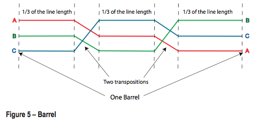
Barrel
A barrel is a section of a three-phase,
high-voltage line of uniform configuration that is divided into three parts of
approximately equal length by two transpositions arranged so that each conductor
occupies each phase position for one-third the length of the line section
(Figure 5).
Impedance Asymmetry
Impedance is the opposition to the flow of
current in an alternating current system. Impedance asymmetry means the
impedances between the phases are not symmetrical, or evenly balanced.
Capacitive Reactance
As the capacitor is charged, an impressed
voltage is developed across its conductive plates. This impressed voltage, which
is referred to as capacitive reactance, opposes the applied voltage and limits
the flow of current in the circuit.
Inductive Reactance
A continually changing magnetic field surrounds
conductors carrying electricity. This field induces voltage in parallel or
adjacent conductors. This induced voltage is always in opposition to the
applied voltage, thereby limiting the flow of current. This current-limiting
characteristic is referred to as inductive reactance.
Inductive Coupling
Inductive coupling is very similar to
inductance, where alternating current flowing through a conductor induces
current flow in an adjacent conductor. The term coupling is used with power
lines inducing current into adjacent open wire communication circuits. This
inductive coupling can result in interference and cross talk on the
communication circuit.
Completely Transposed
When a power line goes through a series of
three transpositions and the phases end up in the same position they were
before the first transposition, the line is referred to as completely
transposed (Figure 6).

Figure 6 – Completely transposed
Why are Transpositions Installed?
In today’s power systems transpositions are
found predominately on trans- mission lines and considerably less on
distribution lines. Transpositions are more beneficial on transmission lines
because of their voltage levels and long length. Transpositions are installed
for the following reasons:
- To reduce the electrostatic and electromagnetic unbalance among the phases which contributes to voltage unbalance. The voltage drops are proportional to the current in each phase when the line has been completely transposed.
- To restrain the amount of current one line induces in a parallel line, which minimizes the arc interrupting duty for the circuit breakers when they are called upon to de-energize the line. Put another way, a circuit breaker has to interrupt a certain amount of current when a line is de-energized. It might include fault current, load current, etc. The current induced from the parallel line must also be interrupted. If this induced current can be minimized it reduces stress on the circuit breaker.
- To help reduce system losses.
- Depending upon their location, they can reduce the inductive coupling of power line currents in adjacent communications lines.
At What Point on the Line are Transpositions
Typically Installed?
The exact location is determined by an
engineering evaluation of the line and any adjacent lines. The line length,
tower geometry, line loading, impedance, voltage levels, and any other factors
may be included in the engineering study. As a general rule, transpositions are
installed at locations that divide the overall length of the line into three
equal sections as shown in Figure 7 below.

The Theory Behind Transpositions
The transmission system should minimize any
unbalance to the energy transported. By design, the geometry of transmission
structures do in fact create unbalances because the distances between the
phases, and the distance between the phases and earth, are not always equal.
These geometric differences can result in unbalanced power flows in an AC
transmission line. The fundamentals of a capacitor are a dielectric substance
sandwiched between two conductors. In the case of a transmission line, the air
serves as the dielectric substance and the line conductors and the earth, or
the grounded structure, are the two conductors, as shown in Figure 8.

Looking at a typical transmission tower
closely it is obvious that the conductors are not always the same distance
apart or the same distance from the earth. It is also obvious that the phase
conductors would not always be the same distance from the grounded structure.
There are many different transmission structure configurations, and geometry
related to the distance between phases and the earth, or the grounded
structure, can vary. This lack of symmetry or equal dimensions results in
unbalanced capacitive reactance between phases. See
Figure 9.
When electric power flows through a
conductor, an electromagnetic field is established around the conductor. The magnitude
of this field is proportional to the voltage and current levels of the line.
These electromagnetic fields induce voltage on adjacent lines.
 As power and communications technologies
developed it became a common practice to install open wire communication lines
parallel to electric power transmission lines or on the same poles as the
transmission lines. It was soon discovered that induced voltages from the power
lines caused interference for the communication lines. It was also discovered
that when transmission conductors crossed each other the electromagnetic fields
tended to cancel each other. This resulted in the practice of installing
transpositions at various points on the transmission lines to minimize the
induced voltages and sub- sequent interference with communications lines.
See Figures 10 and 11.
As power and communications technologies
developed it became a common practice to install open wire communication lines
parallel to electric power transmission lines or on the same poles as the
transmission lines. It was soon discovered that induced voltages from the power
lines caused interference for the communication lines. It was also discovered
that when transmission conductors crossed each other the electromagnetic fields
tended to cancel each other. This resulted in the practice of installing
transpositions at various points on the transmission lines to minimize the
induced voltages and sub- sequent interference with communications lines.
See Figures 10 and 11.


Conclusion
Transpositions are seldom used with new transmission
lines since the modern interconnected transmission grid has evolved. The
unbalance of an un transposed line has been largely mitigated by the phase
balancing effect of the generators, capacitors, and reactors that are
interconnected across the grid. In addition, transpositions are seldom needed
for electromagnetic induction control because inductance problems with
communications lines have all but gone away with underground, fiber optics, and
wireless technology. There are many transpositions in service in older lines
that were prudently installed given the circumstances at that time.
